Control system repair and control system repair
Control and regulation devices are used to automate technical processes, increase convenience and simplify workflows. Visualisation is required so that the user can work with the control or regulation system.

Difference between controls and regulators
Controls and regulators have a very similar function. However, they are not quite the same.
The control system
A control system influences a machine without taking feedback into account.
The regulation
The purpose of closed-loop control is to ensure that the setpoint value is reached and remains constant. A control system measures the controlled variable, processes this signal and outputs a manipulated variable to an actuator. The controlled variable and manipulated variable are called control variables.
What are control variables
The actual and setpoint values are referred to as control variables. The actual value shows the current status or is the currently measured value (e.g. current room temperature). The setpoint is the value that is set by the user (e.g. specified room temperature). The control always tries to adjust the actual value so that it is equal to the setpoint.
What is a Actuator
An actuator is a component that can convert electrical values into physical values.

The PLC as a control system
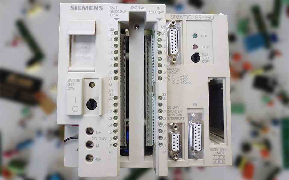
The abbreviation PLC stands for "programmable logic controller". The PLC is responsible for control and regulation tasks on large machines. Sequential languages (AS) are used for programming. A distinction is made between text-based and graphical sequence languages.
Text-based process language
In text-based programming, the instruction list (IL) or structured text (ST) is used. IL is a universally applicable machine language that is very similar to assembler (programming language). Even today it is still frequently used. The ST has a similar structure to the high-level language Pascal. The great advantage is the compact formulation with which complex tasks can be realised.
Graphical process language
Graphical programming can be thought of as a programme interface where you drag in your components and blocks and link them with lines, similar to a circuit diagram. There are two types of programming, the ladder diagram (LD) and the function block diagram (FBD). In the LD, the functions (AND, OR, normally open contact or normally closed contact) are represented from the circuit symbols used in electrical engineering. When programming with the FBD, the symbols of digital electronics are used.

Control and regulation errors
Controls and regulators are extremely complex and versatile assemblies. It is therefore impossible to list or know all the faults. In the following section you will find a few of the most common faults in these components.
Complete failure
The module is no longer illuminated and no actuators are being controlled. On the PLC, both POWER and RUN are dark.
Incorrect control behaviour
The control regulates although there is no deviation. The actual value deviates greatly from the setpoint value. It is also possible that no setpoint value can be set or the actual value can no longer be analysed.
Control of single or multiple actuators without function
Individual or multiple actuators can no longer be controlled even though the input signal is present and being analysed.
Signal input
If the signal input is damaged, the regulation or control system can no longer analyse the value. As a result, the outputs are of course no longer controlled correctly.
Communication error
The PLC or control system cannot communicate with the rest of the system.


